Drawing Instance General OptionsKeyCreator / Layout / Overview / Drawing Instance General Options (1)The majority of new instance settings are controlled through the Create a New Drawing Instance dialog.
Dialog Options: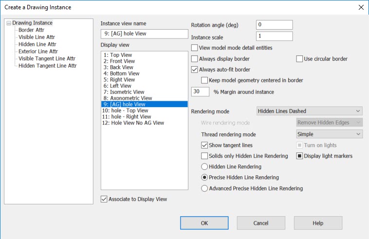 Instance NameSpecify a name for the instance. By default, the Instance name matches the display view. You can type a new name in the text box if you wish. Display ViewThe view in which the part will be displayed in the instance you are creating. Select a view from those available in this field. These views comprise the standard views as well as any user defined or Picture Manager generated views created, (a picture manager view will list with a PM after view name). A user defined view that is created with associative geometry and saved in model mode will list with an AG prefix symbol and the instance will update when the associative geometry is modified in model mode: Example User Defined AG View of Instance: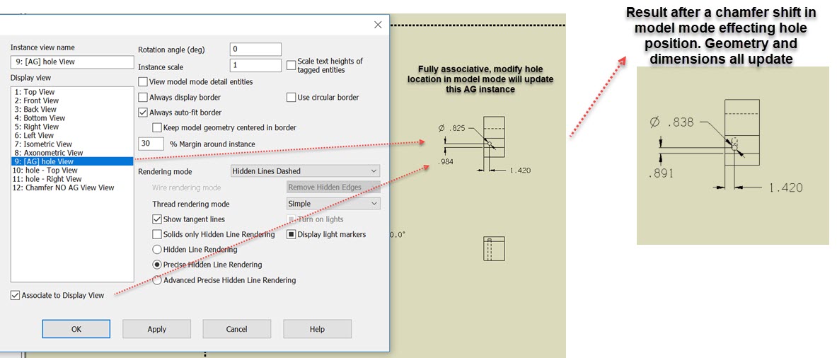 Example User Defined Non-AG View Instance: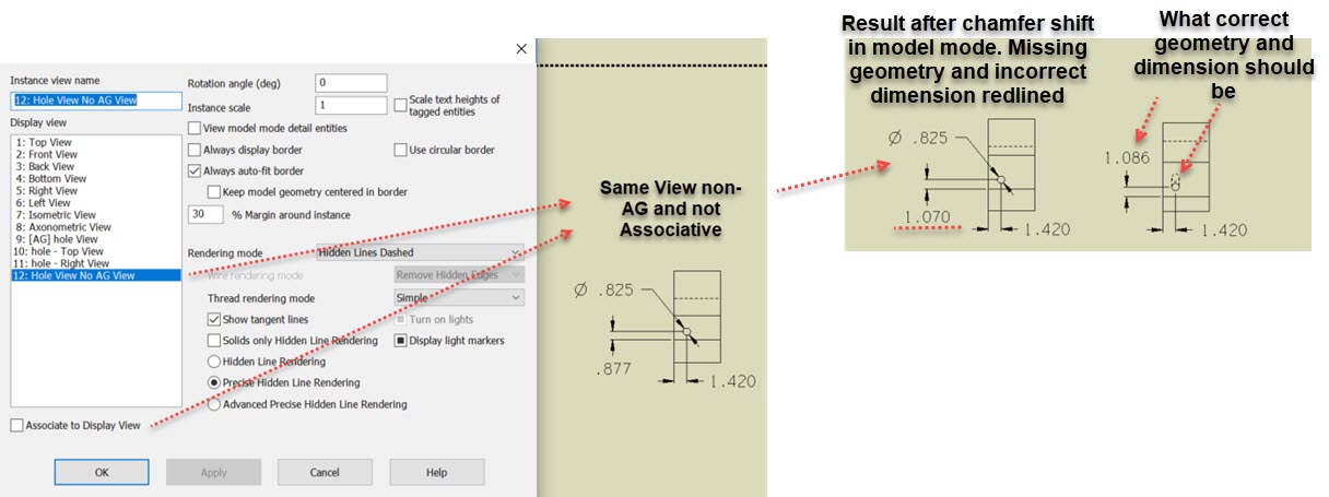 Rotation AngleIn this field, you can enter a rotation angle, in degrees, at which the instance will be placed. Model ScaleHere you can specify a scale for the instance. The system automatically calculates a usable scale size (based on overall drawing layout scale), but you can override this with a specific value by typing it in the input field. View Model Mode EntitiesIf this checkbox is enabled, model mode specific entities (such as details) will be displayed in the instance. Always Display BorderIf this checkbox is enabled, the dotted lines indicating the extents of the instance will be displayed. Circular BorderWhen checked, a circular border will be drawn. Always Auto-Fit BorderWhen checked, the instance border will resize automatically to fit any changes to the model geometry from which the instance is based. Keep Model Geometry Centered in BorderThe effect of this option is seen only in layout mode. This option has no effect when the Always Auto-Fit Border option is cleared. It is used in conjunction with Always Auto-Fit Border selected, as follows:
The geometry displayed within the instance border shifts to keep the instance centered in its border. The instance border does not move.
The instance border itself shifts to encompass the newly displayed and changed geometry. % Margin around InstanceSpecify a whole number from 1-100 for the margin around the instance. The percentage value you enter will determine how much larger the border is compared to the model. Old instances opened from disk will default to a percentage value of 1. NOTE: This field is hidden when the dialog is accessed from the Layout Control dialog. Rendering ModeThis setting allows you to select the rendering mode that will be used to display the part in the instance that you are creating. The available rendering modes are: default,Wire, HLR (Hidden Lines Removed), HLD (Hidden Lines Dashed), Flat shaded, Gouraud Shaded and Phong Shaded. If you want to retain all settings in this dialogue box choose the default option after making your settings selections. Any future sessions will show these last settings if you choose default. Thread Rendering ModeThis setting controls the rendering of KeyCreator Feature and Fastener object threads. See View>Render. Hidden Line renderingThis setting uses existing facet data, and may not require loading of postponed ACIS data. Uses HOOPS PHL rendering. This setting does not support different attributes for exterior lines. Use Rendering Mode to set either Hidden Lines Removed or Hidden Lines Dashed. Precise Hidden Line RenderingThis setting provides better quality rendering, longer rendering times, though it does not support wireframe geometry, which will be included with its regular attributes. Uses ACIS PHL rendering method. Use Rendering Mode to set either Hidden Lines Removed or Hidden Lines Dashed. Advanced Precise Hidden Line RenderingUtilizes new PHL technology developed in KeyCreator 11.0. Highest quality rendering method. Longest rendering time of all HLR options. Use Rendering Mode to set either Hidden Lines Removed or Hidden Lines Dashed. Show Tangent LinesThis setting is only active when either HLR or HLD has been specified as the rendering mode. When checked, tangent lines will be shown. Solids Only Hidden Line RenderingWhen selected, wireframe geometry is not considered when doing the hidden-line computation. It is included as-is on the top of the hidden-line rendering. See Drawing Instance Attributes Tree for descriptions of the attributes panes that are visible when you expand the Drawing Instance tree on the left most pane of this dialog. |