The Plane Definition Menu is used to define a plane in space using orientation and depth. The menu options below appear on the Conversation Bar to allow you to define a plane. The first five menu options (left-to-right) appear in all functions. The View>Display View (shown below) and View>Construction Plane>Set Construction Plane functions add additional options.
Most entities can be selected at the menu in order to define the plane, without having to choose a menu item first. Selecting a line or vector uses that line or vector as the normal of the plane. Other entity types use the entity to define the XY plane.
Menu Options:

3 Pos
Defines the plane based on three positions you indicate.
-
Indicate the first position, which determines the origin of the plane.
-
Indicate the second position. The positive X axis passes through this position.
-
Indicate the third position, which must not be colinear with the first two positions, to define the direction of the positive Y axis.
Line/Pos
Defines the plane based on an X-axis line and a Y-axis direction.
-
Select a line to define the X axis. The end of the line nearest the selection point is the origin, and the other end determines the positive X axis.
-
Indicate a position, which must not be colinear with the line, to define the direction of the positive Y axis.
Nrm/Tan
This option allows you to define a plane by selecting a normal or tangent to an entity at a selected position to be the Z axis of the plane.
-
Select the Pick Pt option to use the position where the entity is selected as the plane origin, or the Exist Pt option for a separate prompt for the plane origin.
-
Select an entity.
-
If "Exist Pt" was selected in step 1, indicate the position for the plane origin.
-
Select either the normal or tangent vector from the viewport to be the Z axis.
-
Indicate a position to determine the X axis.
CP/Dpth
This option defines the plane from an indicated Construction Plane, and offsets that plane along the Z axis by the given Depth.
-
Enter the desired Construction Plane number into the text field, or click the By List button on the Conversation Bar and select the construction plane from the dialog that appears.
-
Choose either Value or Position as the depth-setting method.
-
Set the depth by entering a value or indicating a position. Indicating a position causes the plane to pass through the indicated position, but does not necessarily result in the origin of the plane being at that position.
2 Pos
This option defines a plane based on two positions for the Z axis.
-
Indicate a position for the origin of the plane.
-
Indicate a position for the Z axis. The positive Z axis will pass through this point. The X and Y axis directions are chosen automatically.
Key In
Use the Key In option to rotate the display view or construction plane, as appropriate, by a specified amount about the selected axis. Click the appropriate button on the Conversation Bar to set the rotation direction, enter an angle in the field, and then click Accept to adjust the plane by the specified angle. Each time you click the Accept button, the plane is incremented by the angle value. Select the Done button when you are satisfied with the adjustment.
VPort (CPlane Only)
Use the VPort feature to define the Construction Plane by the display view of a particular viewport. Select the viewport that contains the display plane you want to use.
CPlane (Display View Only)
Use the CPlane feature to set the selected viewport's view to match the current construction plane.
List
Displays a dialog that lists all existing CPlanes or Display Views, as appropriate. The dialog allows you to select a new plane from the eight standard ones or from any new ones you have created previously.
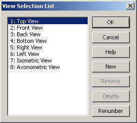
The dialog has several buttons. The Rename and Delete button are not available when a standard one is selected. The New button displays the standard Plane Definition Menu on the Conversation Bar so you can define a new CPlane or Display View. The Rename button prompts you for a new name for the current selection. The Delete button deletes the current selection. The Renumber button automatically renumbers all of the saved CPlanes or Display Views in the part, as appropriate, to remove any gaps in the sequence. For example, if there are three saved CPlanes (9, 10 and 11), and 10 is deleted, leaving 9 and 11, then renumbering changes the number of CPlane 11 to 10.
-
Click the List button on the Conversation Bar. The dialog box appears.
-
Double-click the plane you want to use, or single click the plane and select OK.
Save
This is only displayed when the current CPlane or Display View, as appropriate, is unsaved. This option prompts you for a name and saves it in the active CKD file. Thereafter, you can access it when choosing the List method of defining the plane.
-
Enter a name for the CPlane or Display View in the Conversation Bar, and select Accept.
-
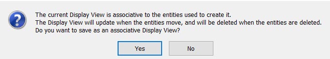
If the unsaved CPlane or Display View is defined associatively to geometry, a dialog box appears, asking if the CPlane or Display View should remain associative. Selecting yes means that the CPlane or Display View will update as the selected geometry changes, but it will be deleted also, when the geometry is deleted, or when it no longer forms a valid plane. Selecting no means that the CPlane or Display View will remain fixed in space, and will not be moved or deleted by any geometry changes.
CP=DV (CPlane Only)
This option enables a mode where the construction plane always matches the orientation of the active viewport. The Construction Plane in this case always passes through the world coordinate system origin, with the positive X axis across the bottom of the screen, from left to right, and the positive Y axis along the left side of the screen, from bottom to top.
DynaDV/DynCP (DynaDV described but same for CP)
This option uses the DynaHandle to set the display view. Once this option is picked a DynaHandle should appear at the display origin, you may need to View>Zoom> Autoscale if it is not displaying. Click on the handle and move as needed to define desired view. Click Accept when done. The resulting display is now oriented on the + blue z DynaHandle .
|