KeyCreator Drafting / Mechanical / Element / Shaft
Use this function to create a shaft entity. The function creates straight and tapered shafts in 2D, 3D and solid representations for rapid creation of rotating machinery models and drawings.
Using the Function
Note: For side representations, after you pick the location for the center of the shaft end, you are asked to choose the axis orientation for the shaft. If you press ENTER at this point, a dialog box appears allowing you to enter the angle into a text field. Dialog Options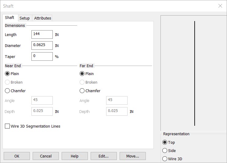 DIMENSIONSLength - The overall length of the shaft Diameter - The outside diameter of the shaft Taper - The percentage of taper from the near end to the far end. The default is 0
REPTop - Creates a 2D top view of the shaft. You are prompted to digitize the shaft center. Side - Creates a 2D side view of the shaft. You are prompted to digitize the center of the shaft end and a location along its axis (or key-in a rotation angel). Wire 3D - Creates a 3D wireframe view of the shaft. You are prompted to digitize the center of the shaft. The shaft will be generated in the –zv direction in the current construction plane.
NEAR END and FAR ENDPlain - Creates a flat end (90 degrees) end condition Broken - Creates a break symbol on the end of the shaft
Chamfer - Creates a chamfered (or beveled) end. When you select this option, the angle and depth fields become active. |