KeyCreator Drafting / File / Properties / Display Colors
The Display Colors pane of the Properties function contains the settings which allow you to customize the colors of your display for each part. The color palette is also available from this dialog.
Dialog Options:
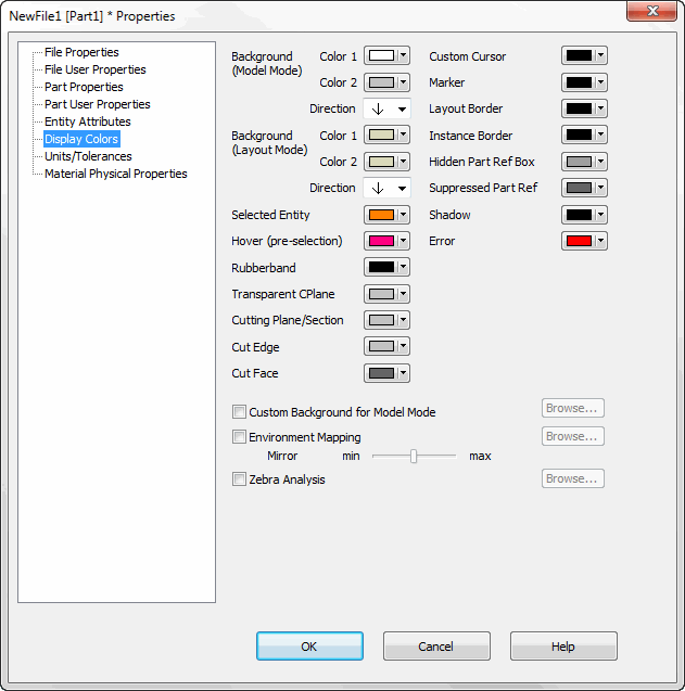
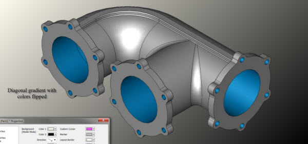
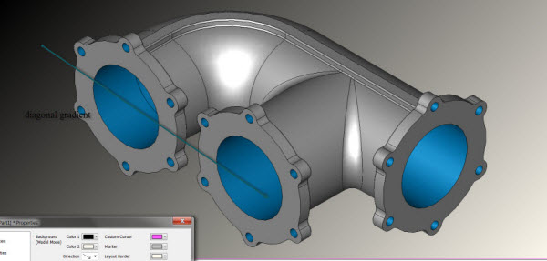
Background - This setting allows you to set a color attribute for the Layout and Model mode backgrounds in all viewports. Top and Bottom input fields are provided that allow you to create a gradient background (one color fades to the other). If you want a solid background, the same color must be chosen for both Top and Bottom. Use the Direction arrow setting to alter the direction of the color gradient, useful in perspective visualization and in presentations. Note that flipping colors 1 and 2 effectively changes the arrow direction (see below.)
-
Selected Highlight - This is the color temporarily applied to the display of selected entities.
-
Dynamic Selection - This is the temporary display color of the entity when you position the mouse over the entity but before you click it. This color helps you see which entity will be selected if the mouse button is clicked.
-
Rubberband - The color of the temporary box or polygon used during many types of selection.
-
Error - Color used for errors. For example, for the Tools>Verify>Body function, it is the color used for any faces that show errors.
-
Custom Cursor - The color of the cursor in all viewports, but only when the Custom Cursor is enabled. Cursor size is set under Tools>Options>Misc. This is also used for axis indicator labels.
-
Marker - The color of the temporary markers used to show locations in the viewport.
-
Layout Border - The display color of the optional layout paper border object.
-
Instance Border - The border color of all instances that do not have a defined color.
Note: If you do not set attributes (all existing instances and the default for new instances), then KeyCreator uses the Instance Border color and, except for Detail Callouts, uses a dashed border. (For Detail Callouts, KeyCreator uses a solid border.)
-
Hidden Part Ref Box - The color of the hidden part reference box in an assembly.
-
Suppressed Part Ref Box - The color of suppressed part references in an assembly.
-
Shadow - The color attribute to be used with the Render Shadow function.
-
Transparent CPlane - The color used for the display of the optional Transparent CPlane which shows the X-Y plane of the active CPlane.
-
Cutting Plane/Section - The color used for the display of Transparent Cutting Plane, Cutting Section, and Slicing Plane objects.
-
Custom Background for Model Mode - When checked, you can browse for a custom background to be used in the KeyCreator viewport. The following image files are supported: BMP, DIB and JPG.
-
Environment Mapping - Select to enable environment mapping. You can browse for the image to be reflected on a solid during shading. The following image files are supported: BMP, DIB and JPG.
-
Mirror - The value specified here is used to determine the reflection of an image. Values from 1-100 (100 max) are supported.
-
Zebra Analysis - Select to enable zebra analysis, which is used to evaluate the surface quality and smoothness of a model. This uses a zebra-pattern image that you specify. You can browse for the image file you want to use. The following image files are supported: BMP, DIB and JPG.
|