KeyCreator Drafting / Detail / Linear / Coordinate Dimension
Use the Coordinate Dimension function to label 2D or 3D points and location coordinates, by generating a dimension entity that describes the X, Y, and optionally, the Z coordinates using various unit and scaling options. Coordinate dimensions are non-associtive, like detail symbols.
Dialog Options: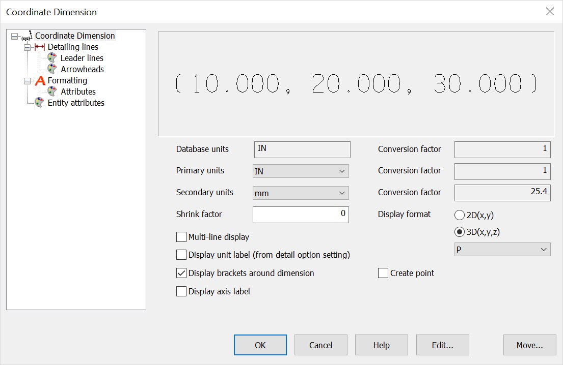 Database UnitsThe database units of current part file. Primary UnitsThis is where you set the primary units for the label. This will be used whenever a label Format with P is specified (e.g., P, P/S, S/P). The scale conversion, in relation to the Database scale is listed in the Primary Scale field. Default value is the Primary detail units in Detail Settings. Secondary UnitsThis is where you set the secondary units for the label. This will be used whenever a label Format with S is specified. The scale conversion, in relation to the Database scale is listed in the Second Scale field. Default value is the Dual detail units in Detail Settings. Shrink FactorUse this field to specify a shrinkage factor to the true dimensions. This option can be used for plastic parts or other design components that shrink from mold to product. The Shrink factor is only used when a Display Format with a lowercase s is specified, and is applied to each dimension (X,Y,Z) as measured from the origin. Display FormatUse this to indicate either 2D or 3D coordinates, as well as which units you wish to include in the label. You can also elect to Create Point, which will include a point when you place the label. To separate the coordinate measure into separate rows use the Multi-Line display. The pull-down list contains 10 possible combinations of the three unit options, which are:
Multi-line displayChecked on this feature will allow for a multi-line represenation and will auto align the X, Y and Z coordinate. Display unit label (from detail option settings)Checked will display the unit label as set in Detail\ Settings\ Options. Display brackets around dimensionChecked will place a bracket around coordinate dimension. Display axis labelChecked will add the X, Y, Z axis label to the coordinate dimension. EDITTo edit the properties of an existing coordinate dimension symbol, select the EDIT button option. Using dynamic selection, left mouse click when the coordinate dimension you want to modify is highlighted. The Edit an Existing Coordinate Dimension dialog will appear allowing you to make the changes you want. MOVETo move a coordinate dimension entity, select the MOVE button option. Using dynamic selection, left mouse click when the entity you want to move is highlighted. Select the new base position using an option from the Universal Position Menu or simply drag the entity to its new location and mouse click to place it. Using the Function:
Above > Example of a Coordinate Dimension |