Feature Control Frame Dialog Options TabKeyCreator Drafting / Detail / Tolerance Symbol / Feature Control Frame / Feature Control Frame Dialog Options Tab
The Options page in the Feature Control Frame dialog allows you to specify additional information relative to the symbol you are creating. Several types of Feature Control Frame symbols allow you to include additional information. When it is possible to add such information, the appropriate input field will be unfrozen.
The symbol that you had created in the main Create a New Feature Control Frame dialog page will appear in the preview portion of the dialog box. Any options you enter for the symbol will be reflected in the preview area.
Dialog Options:
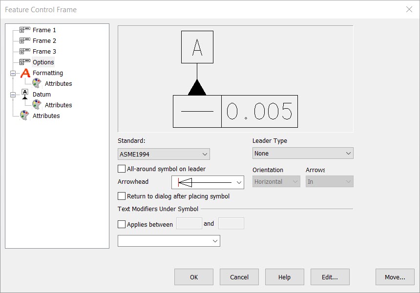
Standard
Select a standard for the Feature Control Frame symbol. The available standards are: ANSI 1982, ASME 1994, ISO, DIN, JIS, and KS.
Miscellaneous Options
Enable the All-around symbol on leader setting to display an all-around symbol on the leader line. To display filled arrowheads, select Use filled arrowheads on leaders. You can elect to return to the Feature Control Frame dialog box after placing the symbol by enabling the Return to dialog after placing symbol setting.
From the Leader Type pull-down, you are able to indicate a leader type to be displayed. The available leader types are: General, Horizontal/Vertical, Under Text/Dimension, String, Linear Dimension, Circular, or None.
For some leader types, you are allowed to set an Orientation and Arrow type.
Leader Types
You can choose from several leader styles for your geometric tolerancing symbol. Some of the leader styles are shown below. To choose a leader, select the type of leader you want from the Leader pull-down list. Leader types can easily be previewed before a specific type is selected in the preview window. The preview will change depending upon what leader type is selected. Explanations of the different types of leaders are given in the following section.
-
General - To create a General leader, pick the endpoint for the leader. Then choose a location for the upper left corner of the tolerancing symbol. The leader will extend from the left or right side of the symbol depending on its position relative to the location of the leader endpoint.
-
Horiz/Vert - For Horiz/Vert. leaders, select an endpoint for the leader. Then choose a location for your symbol. The symbol will be automatically aligned with a horizontal or vertical leader based on the locations you picked.
-
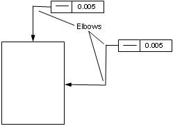
Horizontal/Vertical Segments- As illustrated below, selecting Horizontal/Vertical Segments allows the leader line to have one or two elbows, depending on where you place the leader in the KeyCreator viewport.
-
Under Text/Dimension – This leader type option allows you to place a symbol under an existing detail symbol or dimension. The tolerancing callout will automatically be placed and aligned above or below the last line of text or symbol.
-
String – The String option lets you create multiple leaders. To create a string leader for your tolerancing symbol, pick a location for the first arrowhead and then place the symbol. Next, choose a location for the next arrowhead. When you are done creating arrowheads, press DONE to return to the geometric tolerancing dialog box.
-
Linear Dimension (Gap) – This leader style creates parallel lines to represent the gap. Pick locations for these parallel lines and then select a location for the feature control frame. The Horiz, Vert, and Diag options refer to the orientation of the gap leader on the drawing. The In and Out options refer to the placement of the arrows on the gap portion of the leader; In will place them inside the gap, and Out will draw them outside the gap.
-
Circular – (No Arrows, Arrows In, Arrows Out)- This leader type allows you to place geometric tolerancing symbols directly on holes in your drawing. The No Arrows style will place the leader on the outside of the hole, with no arrows. The Arrows In style will place the leader on the outside of the hole with arrows on the inside of the hole indicating that the entire hole is being dimensioned. The Arrows Out style is the same, except that the arrows are placed outside the hole.
-
Non – If no leader type is necessary, select None. To place the geometric tolerancing symbol, pick a location for the upper left corner of the feature control frame.
Orientation
Specify an orientation for the leader. This setting is active for Linear Dimension (Gap) style only.
Arrows
Indicate an arrow type for the leader. This setting is active for Linear Dimension (Gap) and Circular leader styles. The choices are: In, Out, and Auto.
|