KeyCreator Prime / Solid / Add Feature / Blend / Variable Blend

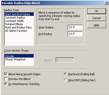
The Variable Blend option is used to blend the edges of a solid with a variable radius. Some of the options in this tab are for the benefit of designers who want non-exact methods of changing the shape of blends. They will be useful for designing parts for which the shape is mostly aesthetic.
NOTE: If a blend operation were to fail, an error dialog appears through which you can elect to create the blend surfaces as sheet bodies. Once this is done, you can use surfacing tools to trim the blend surfaces to the adjacent surfaces of the proposed blend, once modifications have been made to the blend surfaces themselves.
Dialog Options:

Radius Type
Through this dialog, you are able to specify seven different variable edge blend types. These available types are explained below.
-
Start and End Values - The blend radius is computed as a linear taper from starting value to ending value of the edge sequence to be blended.
-
Constant Radius - This option creates a blend that has a constant radius, but whose cross section is non-circular.
-
Constant Width - This blend allows you to enter a width that specifies the distance between the edges of the blend.
-
Rotated Ellipse - This option will create a blend whose cross section is elliptical.
-
Point/Radius Pairs - The blend radius is computed as a function of a smooth curve joining a sequence of points whose radii are provided at certain points along the edge to be blended.
-
2D Spline Function - The blend radius is computed as a function of a 2D curve lying on the X-Y plane centered about the origin. The value along the Y axis represents the radius, while the value along the X axis represents the length along the edge to be blended.
Cross Section Shape
The cross sectional shape options are available for all Variable Radius Edge Blends except Rotated Ellipses. The cross sectional shapes may be varied from circular (the default) to a non-circular spline shape. The default value of 1.0 produces a circular cross section.
-
Circular - Allows for circular cross section spline shapes. The default value of 1.0 produces a circular corss section.
-
Thumb Weighted - When the thumb weight values are increased from 1.0, the blend tends to bunch up and when the values are reduced below 1.0, the blend flattens out. Thumb weighted geometry is constructed of splines. Note this differs from other blend types that are composed of arcs.
When entering thumb weight values keep in mind that as the thumb weight value approaches infinity, the cross section tends to a sharp corner. As it approaches zero, it tends towards a pure chamfer. The highest (1,000,000) and lowest (1e-9) thumb weight values indicate the maximum stretching or squeezing of the cross sectional shape.
Thumb weight values affect the shape of the cross section. Think of it this way. Put your thumbs on the edge of the blend and apply some pressure to "squeeze or push" the blend cross section. Entering thumb weight values less than 1.0 has the reverse effect. Your thumb "pulls or stretches" the blend cross section and flattens it out.
NOTE: Thumb weights are entirely for aesthetics. Note that working with thumb weights will require a lot of trial and error. There is no way to get an exact desired shape, only an approximate shape can be obtained. You will need to adjust the numbers until you achieve the results that you desire.
|

Thumb weights = 4.0
|

Thumb weights = 0.4
|
-
Blend Along Smooth Edges - When you need to blend connected edges that continue smoothly (no abrupt change in tangent) from the selected edges, select the Blend along smooth edges checkbox.
-
Preview the Blend - When selected, you will be able to preview the blend result before accepting that result. This is a useful feature, as it allows you to preview and make changes to the blend before the selected edge(s) is actually modified by it.
To end preview of the blend surfaces when the checkbox is active in the dialog box, click ACCEPT to complete the blend operation, BACKUP to return to the dialog box, or ESC to cancel the blend.
When previewing the blend, you may use immediate mode commands to dynamically pan, zoom and rotate the model in order to view the preview surfaces from any angle.
-
Do Interference Checking – Will allow for check for features that might interfere with the path of the blend surface and allows the blend to complete properly despite the interference. Interference's such as holes, protrusions or other geometric features normally would cause the blend to fail or to complete but cause a self-intersecting solid. Enabling this checkbox prevents self-intersections from occurring and allows the blend to complete properly.
-
Machined (Rolling Ball) – Rolling ball is a traditional profile that travels perpendicular to the blend edge. This produces blend geometry that replicates a machining tool.
-
Wire EDM (Sliding Disc) – Sliding disc is a circular profile that travels in a fixed direction. This produces blend geometry that replicates a wire EDM tool.
Using the Function:
-
Select Variable Blend from the Solid>Add Feature>Blend Ribbon area. The Variable Radius Edge Blend dialog appears (see above).
-
Configure the dialog settings, and click OK.
-
Select the edge to be blended.
|

