KeyCreator Prime / Solid / Add Feature / Holes / Tapped Hole

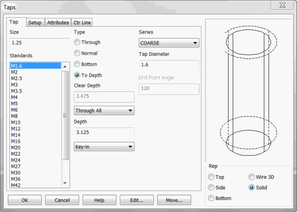
You can create a tapped hole by selecting the Tap icon from the Features Menu. Enter the information about the feature in this dialog box. Your selections will be reflected in the Preview window.
If you wish, you may click the KEY-IN button (at the bottom of the dialog box) in order to enter the parametric values for the feature manually.
Dialog Options:

Size
Select a Size for the feature. You may choose from either the list of Standards or enter a custom size in the text field.
Type
-
Through - A through tapped hole is a tapped hole that extends completely through to the bottom surface from the top surface on which it is created.
-
Normal - A normal tapped hole is created with a tap drill generally four coarse thread pitches deeper than the tapped hole depth.
-
Bottom - A bottom tapped hole is created with a tap drill generally one coarse thread pitch deeper than the tapped hole depth.
-
To Depth - A tapped hole created to depth is drilled through and tapped to a specified depth.
The extra depth of normal and bottom tapped holes can be configured to your specifications. See the Setup section at the end of this chapter.
Series
-
Choose a Series for the hole from the pull down list. You can choose a UNC, UNF, or UNEF series (i.e., coarse, fine, or extra fine).
-
If To Depth was selected, you can select a Tap Depth, otherwise this option will be "frozen." You may Key-in a depth or choose another option from the pull down list to specify the tap depth. The other options are described in step 6.
Tap Diameter
This reflects the overall tap diameter seen in the preview pane as a dashed line representation (associated with outer edge of threads.)
Drill Point Angle
Sets the bottom angle of the drilled hole. When the Bottom/Normal method is checked on manual entry is possible.
Clear Depth
Select a clearance Depth. You can Key-in a depth in the text field or click on the pull down list for more options when To Depth Type is selected. This depth reflects the overall depth of drill hole. Your other choices are:
-
Line - Select an existing line. The line's length will be used as the feature's depth.
-
2 Pts. - Choose two points to indicate the depth. The feature's depth will be the distance between the two points.
-
Plane - Select a plane to indicate the feature depth. The depth will be the distance from the current construction plane to the selected plane. The selected plane must be parallel to the XY plane of the current Cplane.
-
Through All - Choose this option to make holes through all apposing faces (after selecting the start face.)
-
Up to next face - Choose this to pick a face that has an apposing face you wish to stop at (you will be prompted for a face to start and then a face to stop.)
-
Up to face - This option will place the hole through multiple apposing faces after choosing the initial face and will stop at a chosen stop face.
Depth
Choose a depth for the overall depth of the hole. You can key-in a depth in the context field (for all but the Through Type) or click on the drop down for additional options. This can be seen as the usable area depth . If the Type =Through you will see the last 3 choices as options (through all, up to next face and up to face.) Your other choices are:
-
Line - Select an existing line. The line's length will be used as the feature's depth.
-
2 Pts. - Choose two points to indicate the depth. The feature's depth will be the distance between the two points.
-
Plane - Select a plane to indicate the feature depth. The depth will be the distance from the current construction plane to the selected plane. The selected plane must be parallel to the XY plane of the current Cplane.
-
Through All - Choose this option to make holes through all apposing faces (after selecting the start face.)
-
Up to next face - Choose this to pick a face that has an apposing face you wish to stop at (you will be prompted for a face to start and then a face to stop.)
-
Up to face- This option will place the hole through multiple apposing faces after choosing the initial face and will stop at a chosen stop face.
Representation
Choose a Representation (view) for the feature: Top, Side, Bottom, Wire 3D or Solid. Wire 3D and Solid representations are created in the -ZV direction.
NOTE: Solid representations of tapped holes have been improved. Tapped features created or subtracted from a solid have been modified to create a hole of the minor diameter size and create wireframe entities at the major diameter. Two dashed circles with join lines will represent the major diameter. This will better conform to how tapped holes are depicted when drafted.
For information on the other tabs in the dialog see Setup, Attributes and CTR line
| 