Bearing and BushingKeyCreator Prime / Mechanical / Element / Bearing and Bushing
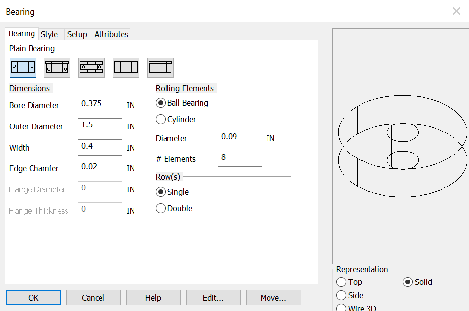
Use this function to create a bearing or bushing entity. The selections you make on this dialog box affect what you see in the preview window on the right side of the dialog box. Using the Function
Note: If you attempt to create invalid geometry (for example, a bearing with a bore diameter larger than the outer diameter), an error message appears.
NOTE: To create a 2D side profile, digitize the center of the bearing or bushing end and a point along the shaft or bearing axis. For a top profile, digitize a center location for the bearing or bushing. For side representations, after you pick the location for the center of bearing or bushing end, you are asked to choose the axis orientation for the bearing or bushing. If you press ENTER at this point, a dialog box appears allowing you to enter the angle into a text field. For a plain 3D or solid bearing or bushing, the digitizing position is located at the center of the bearing at its end. For a 3D, solid bearing or bushing with a flange, the digitizing position is located at the center of the flanged diameter. 3D and solid bearings or bushings are drawn in the –zv direction in the current construction plane.
Dialog Options 
TYPE OF BUSHING OR BEARING BUTTONSPlain Bearing, Flange Bearing, Thrust Bearing, Plain Bushing, Flange Bushing
REPTop Hidden - Top view with hidden lines dashed Top Outside - Outside lines only showing in top view Side Hidden - Side view with hidden lines dashed Side Outside - Outside lines only showing in side view Side X-Section - Cross-section of side profile of radial bearing without join lines Side Join X-Section - Same as Side X-Section with join lines across bearing or bushing inside diameter Wire 3D - 3D view of bushing or bearing. Shaft is drawn in the –zv direction Solid - A 3D solid primitive is created using solids
DIMENSIONSType a bore diameter, outer diameter, width, edge chamfer.
ROLLING ELEMENTSSelect a rolling element type: Ball bearing or cylinder
DIAMETERType diameter for the ball roller or cylinder
#ELEMENTSType the number the elements you want to have in the bearing. Maximum number is calculated as [Outer Diameter + Inner Diameter ÷ 2 x ð]
ROWSThis applies only to ball bearings. Select single or double.
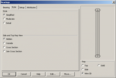
STYLESimplified - Envelope of the bearing or bushing Moderate - Envelope with chamfered corners Detail - Envelope with chamfered corners and roller elements Schematic - Simplified diagram view for use in schematic drawings |