Extrude Planar Profile Dialog OptionsKeyCreator Prime / Solid / Create / Sweep / Extrude / Extrude Planar Profile Dialog Options
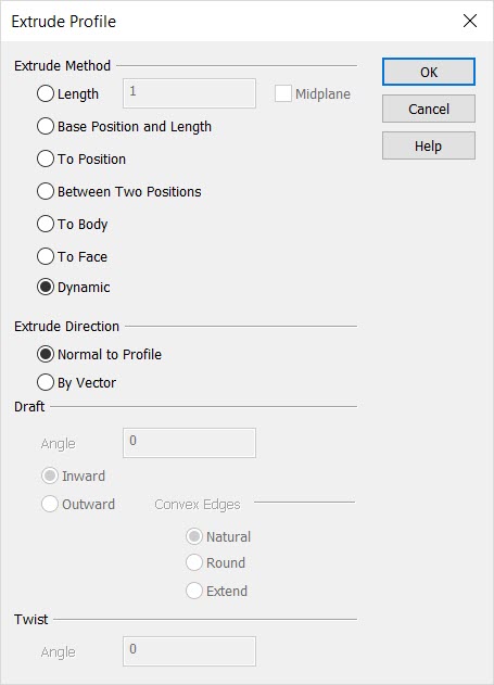
When Sweep>Extrude is selected, the Extrude Planar Profile dialog box is displayed. Contained in this dialog box are several settings that allow you to specify how exactly an extrusion is to be created. The segment below will discuss the several options available to you from the dialog box.
Dialog Options:
End Method
Chose an end method, or, how the extrusion end is to be defined.
-
Length - When selected, you are prompted to indicate a length value. The extrusion will be created to this indicated length.
-
Midplane Extrusion - when enabled, allows the profile to be extruded by half the distance in both directions when extruding by length OR by the profile-position distance when extruding to a position.
-
Base Position and Length - Allows for directional extrude based on a positive or negative value from base position.
-
Extrude to Position – This option allows you to select a position to determine the length of the extrusion. As with the length option, once the profile is selected, you are prompted to either select normal vectors or a vector direction based on the direction option. You are then prompted to select the position to extrude to. Note that the position is only used as a measure of the distance. The vectors selected in the previous step determine the direction of the extrusion. You are also able to do a midplane extrusion with this end method. In this case the profile-position distance is used to extrude the profile in the two opposing directions.
-
Extrude to Body - Extrude to Body allows the extrusion to be trimmed to the intersection of another body. If extrude to body is enabled the mid plane extrusion option is grayed out.
-
Extrude to Face - Allows you to define where the extrusion terminates by selecting a face of an existing body. The terminating face of the extrusion will be the projection of the profile curve on the chosen face of the other body along the extrusion direction vector. The face used to project onto does not need to be planar. If it is not planar, the terminating face of the extrusion will not be planar either. If extrude to face is enabled the mid plane extrusion option is grayed out.
-
Dynamic- Uses a DyanHandle placed either normal to profile or direction vector. Once the closed planer profile is selected, left click and drag the DynaHandle to desired position or right click and use the context menu for positioning. Note that as the DynaHandle is moved there remains another DynaHandle in the original position, which can also be moved
Midplane extrusion, when enabled, allows the profile to be extruded by half the distance in both directions when extruding by length OR by the profile-position distance when extruding to a position. When extruding by mid plane there is no prompt to select the extrude direction. If a draft angle is also specified, an equal draft is applied in each direction. The length of the extrusion is entered in the Distance box.
Above > Example of an extrude created by the Extrude to Body end method
Direction
Indicate a direction vector for the extrusion being created.
-
Normal to Profile - Once the curves have been selected, you will be prompted for the extrusion direction vector to determine the direction of the extrusion. Two vectors will be created temporarily for this choice, each normal to the plane of the curves, one up, one down. Select one of these vectors to define the direction for the extrusion.
-
By Vector - After you select the profile curves, the Vector Selection Menu will allow you to choose the extrusion direction. You can choose to define the vector from:

Draft
The options in the Draft Properties section allow you to shrink or expand the profile curve as it is extruded.
-
Angle - The Draft angle is measured from the extrusion vector. When you do not want a draft added to the extrusion, leave the draft angle set to 0°. In this case the result will be a vertical extrusion. Negative draft angles are no allowed. To achieve a tapering extrusion, select Inward in the Draft drop down list. To have the extruded face grow larger in area as the draft is applied, select Outward from the list.
-
Inward - When a profile with inner loops is extruded with a draft angle, the inner loops will go in a direction opposite to that of the outer loop. For example, if the extrude is performed Outward the outer loop will draft outwards and the inner loops will draft inward.
-
Outward - When using the Draft>Outward option, you can choose how to fill in gaps created by extruding a profile outwards. The options are:
-
Natural - draws two straight tangent lines from the ends of each segment until they intersect.
-
Round - creates a rounded corner between the two segments.
-
Extend - extends the two shapes along their natural curves, e.g., along the circle and along the straight edge, until they intersect.

Above > Gaps and Natural, Round, and Extend draft methods.
Twist
While a profile is being extruded, Twist angle allows for the profile to be twisted by a given angle.
-
Angle - The twist angle is the total angle in degrees that the profile will be twisted. Twisting is accomplished about the extrusion path. The extrusion path is usually located at the approximate center of the profile. Since the location of the extrusion path is not user controllable (only one direction), it may be desirable to use the Sweep feature to get a precise twist.
|