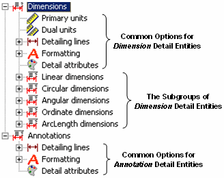
How the Detail Style Editor Dialog Itself WorksKeyCreator Prime / Home / Styles / Style Editor / How the Detail Style Editor Dialog Itself WorksThe Detail Style Editor dialog appears when you click Detail>Settings>Style Editor. When you expand the Dimensions and Annotations nodes, the subnodes identified below appear. Notice that the two top-level nodes account for the two major kinds of detail entities mentioned previously (dimension and annotation). Notice also the second-level nodes. Primary units through Formatting, under Dimensions, are termed common options for dimension detail entities. Detailing lines plus Formatting are termed common options for annotation detail entities. The remaining second-level nodes under Dimensions are expandable nodes that account for each subgroup of dimension detail entities (Linear dimensions through ArcLength dimensions). 
The significance of "common options" is explained next. Common Options Versus Local Options
Several of the second- and subsequent-level nodes are shown expanded in the figure below. Notice that subnodes under Linear dimensions have the same name as higher-level nodes above them. For example, there is a Primary units node directly under Linear dimensions and there is a Primary units node directly under the higher-level Dimensions node. There is an Extension lines node under Dimensions>Linear dimensions>Detailing lines and there is an Extension lines node under Dimensions>Detailing lines. Of course, when you click a node, the corresponding pane for that node appears, with a variety of options for you to configure as desired. For a detail entity kind (dimension or annotation), when the same node name appears, the options at the higher-level are called common options and those at the lower level are called local options. So, for example, the options that appear on the pane when you click Dimensions>Detailing lines>Extension lines are common options and those that appears when you click Dimensions>Linear dimensions>Detailing lines>Extension lines are local options. The higher-level determines the lower level, unless you configure a local level differently. Precisely stated, here is how the Details Style Editor dialog works:
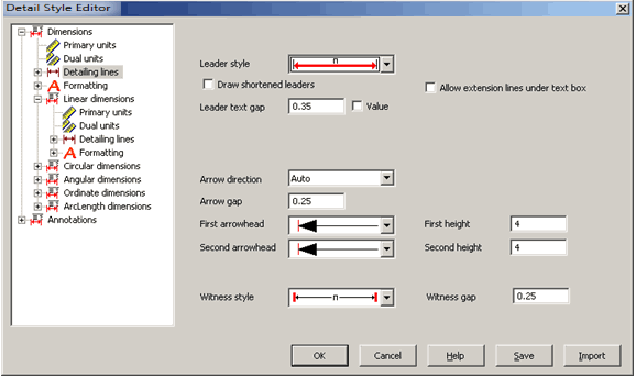
Let us look at an example of using the Detail Options dialog Example Using Linear Dimensions1. Click Detail>Settings>Style Editor>Dimensions>Detailing lines. The common Detailing lines pane appears, as shown below. Notice the settings. 
2. Click Linear dimensions>Detailing lines. The local Detailing lines pane appears, as shown below. Notice that the common and local panes have similar options, except that the local pane has yellow fields and an additional check box for each field. The yellow indicates that the values in those fields are the same as set in the common pane. The additional check boxes, located to the left of each field, are called local-use check boxes. A local-use check box allows you to override the common option with the value you specify. When you clear the local-use check box, the field
When you select the local-use check box, the field
3. Select the Arrow direction check box and select In.
4. Select the First arrowhead check box and, in the First arrowhead field, select the slanted-line arrowhead. The pane appears as shown below. Notice that, as expected, the Arrow direction and First arrowhead fields are not highlighted in yellow. All other fields on this pane are highlighted in yellow, indicating they have the same values as those set for the common options. The common-versus-local behavior just described for Linear dimensions is the same for the remaining Dimensions detail entities (Circular, Angular, Ordinate, ArcLength) and for Annotations. Click the link below to continue the explanation of using the Detail Style Editor dialog. How Detail Style Editor Affects Newly Created Detail Entities
|