KeyCreator / Tools / Feature / Countersunk Hole
To create a countersunk hole, enter the information about the feature in this dialog box. Your selections will be reflected in the Preview window. If you wish, you may click the KEY-IN button (at the bottom of the dialog box) in order to enter the parametric values for the feature manually. Dialog Options: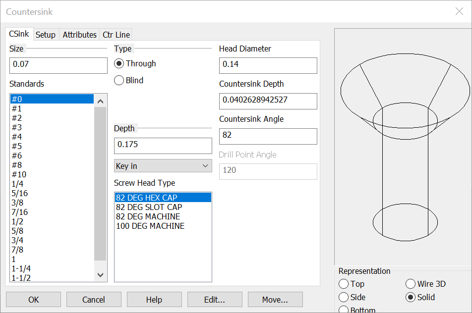
SizePick a Size for the hole from the list of Standards, or enter a size in the text field. Type
Head DiameterInput the top head diameter for the countersink representation if the standard input is not the intended diameter. Countersink DepthInput the top head depth for the countersink representation if the standard input is not the intended depth. Countersink AngleEnter the counter sink chamfer angle if the standard angle is not the intended angle. Drill Point AngleWhen the Blind type is chosen the drill point angle will be available to edit as needed. DepthChoose a Depth for the hole. You can Key-in a depth in the text field or click on the pull down list for two other options. For the Through Type the last three options become available (through all, up to next face and up to face) Your other choices are:
Screw Head TypePick from the standard list of counterbore screw head types representations. This will update the options to fit that representation. RepChoose a Representation (view) for the feature: Top, Side, Bottom, Wire 3D or Solid. Wire 3D and Solid representations are created in the -ZV direction. For information on the other tabs in the dialog see Setup, Attributes and CTR line |