|
KeyCreator / Tools / Application Options / Solids The Solids page contains settings options related to 3D bodies (solids, surfaces, and shells). Dialog Options: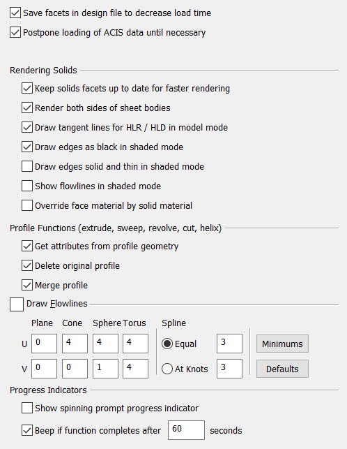
Save Facets in Design File to Decrease Load TimeTo display solids in a rendering mode other than Wireframe, the faces of the solids must be faceted. Faceting creates a mesh of triangles that approximate the face. When this setting is enabled (checked), the facets are saved with the solid. When disabled, the facets are ignored during File>Save and discarded when the part is closed. Each time the part is opened, the facets are recreated. This requires that the solids data be loaded from disk. As a result, saving the facets reduces load time, as well as the amount of data that has to be loaded, reducing file size. Postpone Loading of ACIS Data until NecessaryWhen enabled (checked), the ACIS precise geometric data for solids and surfaces are not loaded from the design file until an operation is performed which requires the data. This reduces the amount of time and memory required to load a part. If the facets are saved in the file (see above), rendering and non-solid operations can be immediately performed, with no further file access required. This will, however, cause an increase in time for the first operation on each solid that requires ACIS data. Disabling this setting will cause all of the ACIS data for each solid to be loaded during the initial load of the part, increasing both the load time and memory usage. Disabling this setting while parts are open will load any solids that have not yet been loaded, creating a state in the Undo system. For this reason, this setting cannot be changed when the page is accessed during a modeling operation. Rendering Solids
Profile Functions
Draw FlowlinesYou have the option to display U and V lines in solid bodies that you create, and can specify the number of U and V display lines using the Draw Flowlines setting. This is a checkbox setting that, when enabled, will allow for U and V lines to appear in solids. NOTE: These flowline settings will only affect solids created after the change is made. To change the flowline representation on existing solids, use the Edit>Entities>Change Flowlines function. Solids are represented by a two-dimensional display of U and V lines. The 3D surface representation of objects is determined by the parameters that increase/decrease in both the U and V directions. Through the settings available from the Draw Flowlines segment of the "Solids" dialog page, you are able to specify the number of U and V lines to represent the following: Plane, Cone, Sphere, Torus, and Spline. The valid range for each are listed below:
The MINS and DEFS buttons in the dialog can be used to set the U and V line settings to either their minimum or default settings, respectively. The Spline options "Equal" or "At Knots" control where flowlines are drawn on spline faces (for anything that is not a plane, cone/cylinder, sphere or torus). When ”r;Equal” is selected, the specified number of flowlines are drawn and spaced equally in the U and V direction. When ”r;At Knots” is selected, U and V values are not specified, and flowlines are drawn at U and V values known as Knot Values. There are at least two (2) knot values in both the U and V directions, commonly referred to as ”r;patch boundaries.” The number of knots is different for each face. Progress IndicatorsThe Progress Indicators allow you to view the status of an active operation. Select "Show spinning prompt progress indicator" to display the spinning prompt indicator. When the "Beep if function completes after x seconds" setting is enabled, you are able to specify when the beep prompt will activate. The beep indicator will sound at the end of any solids operation that takes longer than the specified number of seconds. |